

Aleksander Burd - website of analog electronics
LCg-1 - a structural LC oscillator, base version
19-04-2020
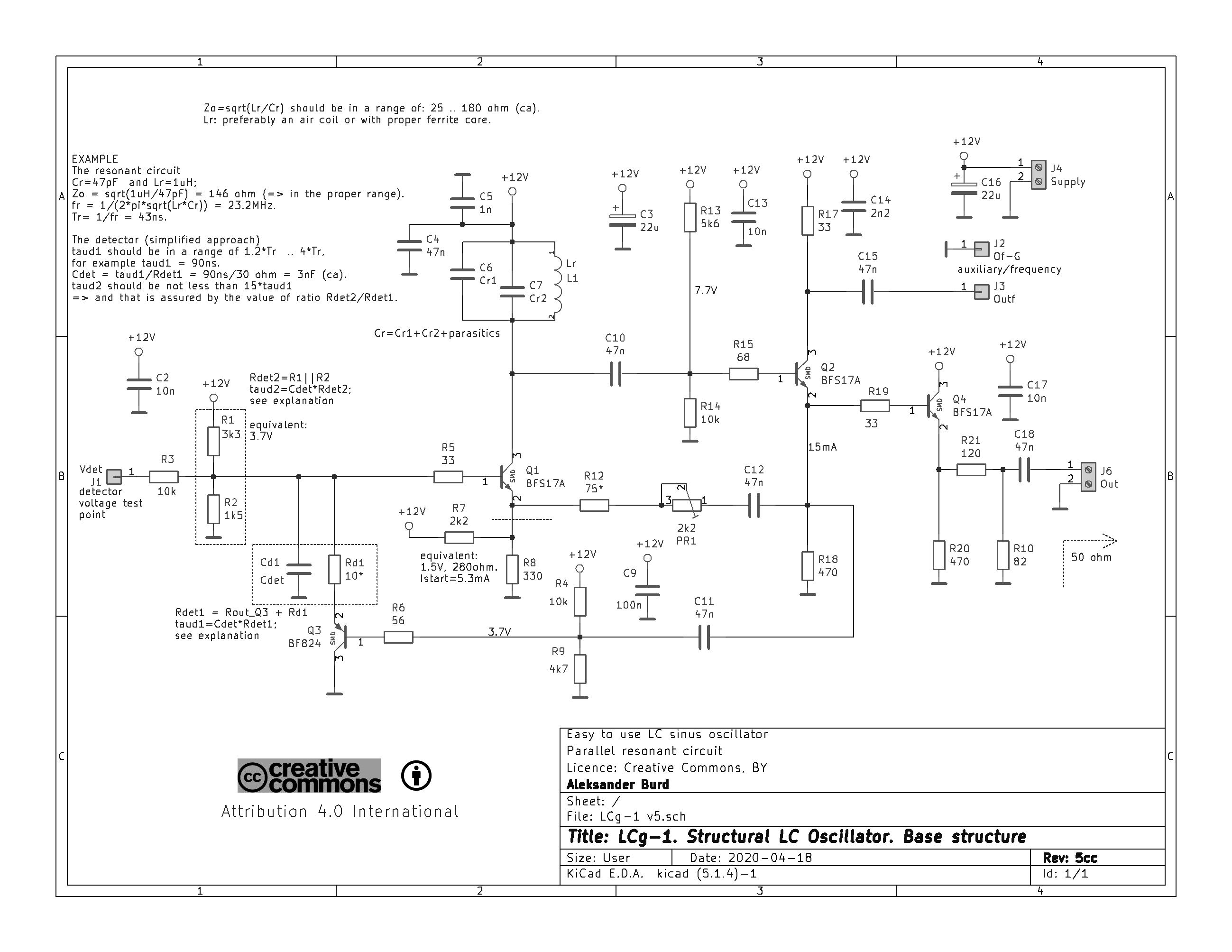
The LCg-1 is a structural LC oscillator that generates a sinusoidal signal.
One can say that it is easy-to-use LC oscillator but it is truth only for experienced electronics engineers. This schema cannot be recommended for beginners.
The system does not contain a reactance divider (capacitors in
Colpitts, coils in Hartley) or a transformer (in Meissner). The presence of these
circuits in classic oscillators make it extremely difficult for
frequency tuning. Because changing resonant frequency affects the
strength of positive feedback as well.
There is no such problem using LCg-1oscillator.
The LCg-1 oscillator is a LC oscillator. It means its most important subcircuits have well define functions:
- resonant amplifier (common base configuration): Q1, Cr, Lr;
- positive feedback (PF) loopback: C12, PR1, R12;
- negative feedback (NF) loopback: R4-R9, Q3, Rd1, Cd1.
The Q2 follower has the obvious function of a resonant circuit: it's buffer, while the Q4 is the output follower.
Transistor Q3 is not a classic follower: its function is to the
amplitude detector of the generated signal. This transistor is cut off for the part
of the period.
In the classic Colpitts oscillator, the resonant
circuit consists of three elements: a coil and the two capacitors. The LCg-1 frequency generation depends on only two elements: Lr and Cr. The Q-factor of the Lr and Cr elements affects the positive feedback loopback: greater
Q-factor - greater gain. The PR1 element is used to adjust the PF level.
This makes it much easier to set up this oscillator.
Only three elements need to be set in the circuit: Lr and Cr in the
resonant circuit and the Cd1 - detection capacity. Additionally, the PR1
potentiometer should be used to set the level of positive feedback. The selection of these elements is easy because their functions are separated:
the values Lr and Cr set the frequency, Cd1 sets the response of the
detector, and PR1 sets finally the amplitude. If these elements are correctly chosen, the oscillator will work correctly.
The range of generated frequencies for the given elements is about
150kHz .. 60MHz. The lower frequency results from the coupling between
stages and can be reduced without any problems. The
capacities between the stages (mainly C12) should be increased for this purpose. The
upper limit of frequency results from the transistors used.
The first version of the LCg-1 oscillator had been created in 2002, it was
used later in many constructions and several diploma theses.
Over the years of work on LC oscillators, I have also built other forms of structural oscillators that I will publish here.
Over the time, the description of the above structure will be expanded - the LCG-1 oscillator is certainly very valuable and it deserves reliable
description.
I added a PCB design (full Kicad v5 project with gerbers) - see "Download" below.
Aleksander Burd
Download

Structural LC oscillator by Aleksander Burd is licensed under a Creative Commons 4.0 License.